Français
 Español
 Deutsch


Content
- 1 Introduction
- 2 Why Insert Removal Requires a Dedicated Tool
- 3 Product Overview
- 4 Core Design Advantages
- 5 Comparison with Improvised Removal Methods
- 6 Manufacturing Strengths Behind the Product
- 7 Manufacturing Process Considerations
- 8 Recommended Operating Procedure
- 9 Application Areas
- 10 Selection and Maintenance Guidance
- 11 Quality, Supply, and Customization Support
- 12 Frequently Asked Questions
- 12.1 What is an insert removal tool used for?
- 12.2 What insert sizes does this tool support?
- 12.3 Can the tool remove every type of thread insert?
- 12.4 Will removal damage the original base thread?
- 12.5 Can it be used on aluminum components?
- 12.6 Is it suitable for field maintenance?
- 12.7 What should be done if the insert does not move?
- 12.8 How should the tool be stored?
- 12.9 Can the manufacturer provide related products?
- 12.10 What information is useful when requesting a quotation?
- 13 Conclusion
- 14 References
- 15 Product: Insert Removal Tool
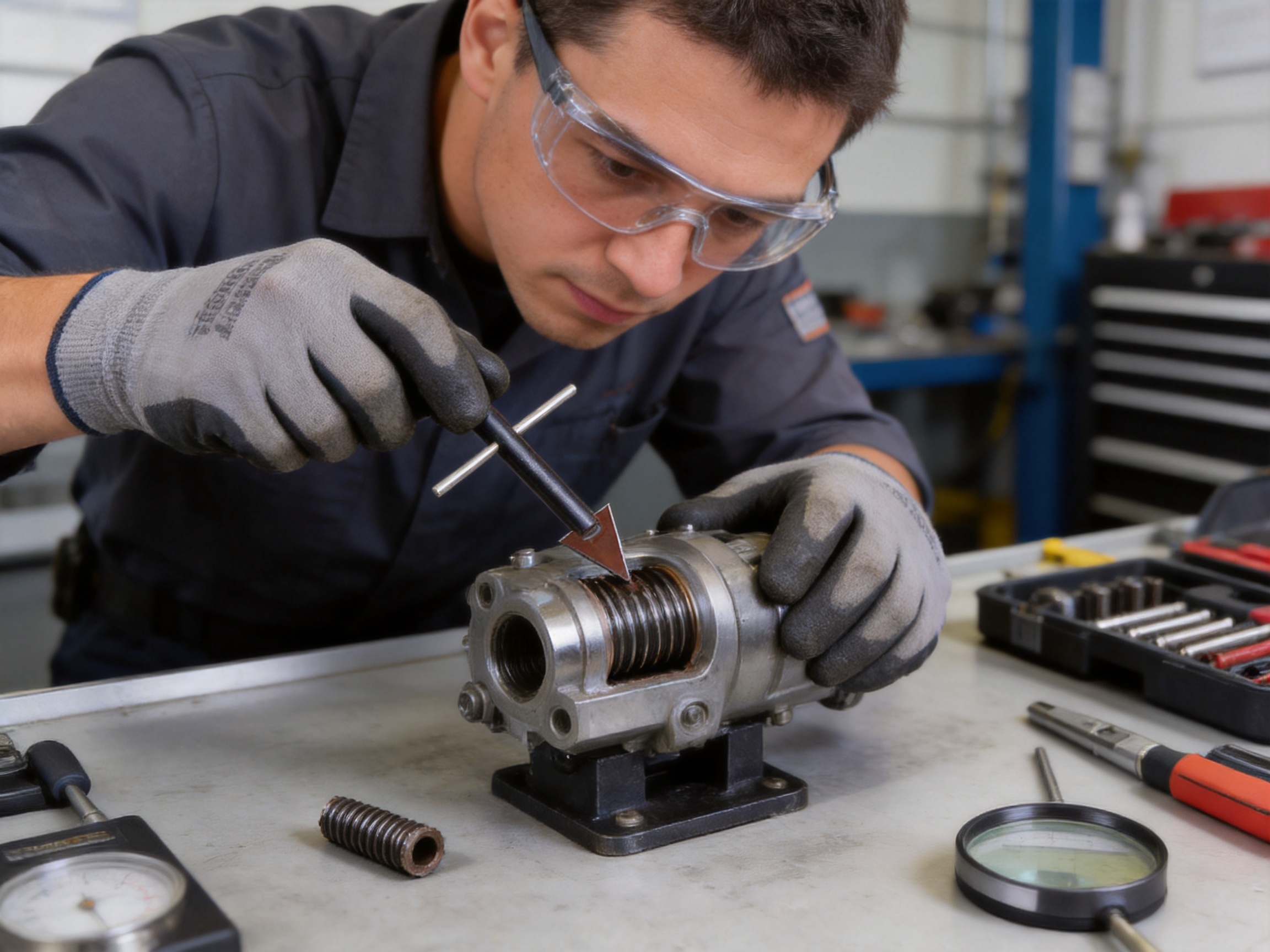
Introduction
Thread inserts are widely used to restore damaged threads, reinforce tapped holes, improve wear resistance, and create reliable threaded connections in materials that may not provide sufficient thread strength on their own. They are found in engine components, transmissions, aerospace structures, rail vehicles, industrial equipment, electronic housings, and many other assemblies. When correctly selected and installed, a thread insert can provide a durable and repeatable fastening point. However, even a high-quality insert may need to be removed if it is incorrectly installed, damaged during assembly, deformed by excessive torque, contaminated, or no longer suitable for the application.
Removing an insert is often more difficult than installing one. An installation tool is designed to drive an insert into a prepared hole, while an extraction tool must overcome the insert’s grip without damaging the internal and external threads of the base material. Improper removal can enlarge the tapped hole, distort the parent material, create burrs, or leave metal fragments inside a precision component. These problems may require the replacement of an expensive part instead of a simple insert repair.
The Insert Removal Tool is designed specifically for controlled extraction of incorrectly installed, damaged, or stuck thread inserts. Its gripping geometry, high-hardness alloy steel construction, and force-distribution design allow operators to remove inserts while protecting the original base threads. Compatible with multiple insert sizes from M3 to M16, the tool supports a broad range of maintenance and production requirements.
Manufactured by Dongtai Jinzhize Metal Products Co., Ltd., the tool forms part of a broader range of threaded connection and fastening products, including helical wire inserts, self-tapping inserts, key-locking inserts, threaded adapters, oil plugs, installation taps, and related accessories. The manufacturer’s experience in thread-related products enables the removal tool to be developed with practical knowledge of insert geometry, installation behavior, and repair requirements.
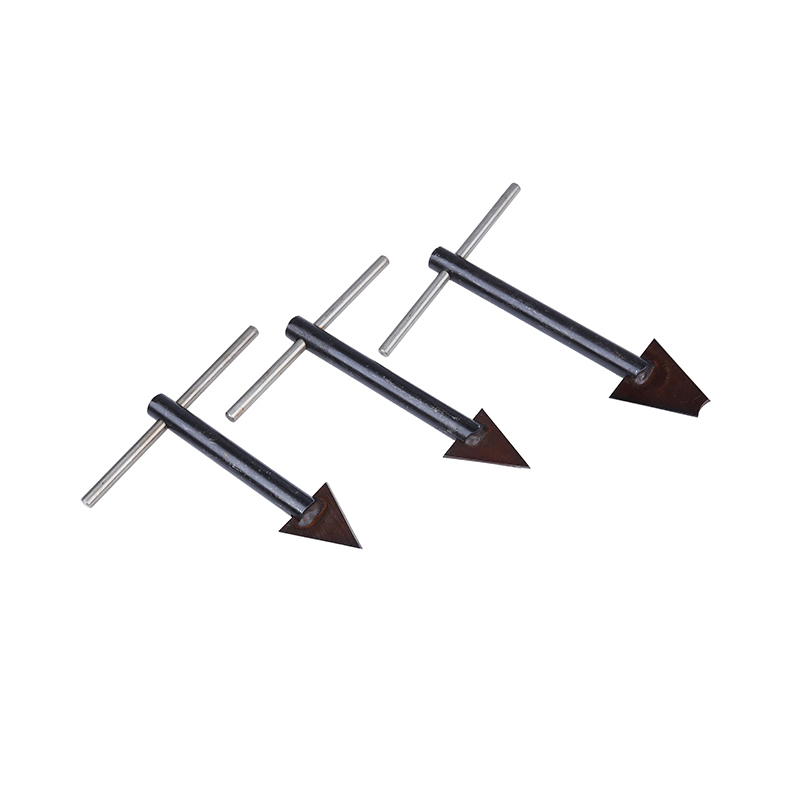
Insert Removal Tool
Why Insert Removal Requires a Dedicated Tool
A thread insert is held in place by the interaction between its external profile and the tapped hole in the base material. In the case of a helical wire insert, the coil is compressed into the internal thread of the parent material. Self-tapping inserts may use cutting or forming features to establish their own external engagement. Key-locking inserts can include locking keys that expand or anchor the insert after installation. Each design presents different extraction challenges.
When an insert is damaged, the internal thread may no longer accept the fastener. The insert may also be installed below the specified depth, above the surface, at an incorrect angle, or with insufficient tang removal. In other cases, corrosion, adhesive contamination, cross-threading, or excessive tightening can lock the insert in place. A general-purpose plier, screwdriver, punch, or improvised cutting tool may provide insufficient control and may damage the surrounding hole.
A dedicated removal tool addresses these problems through several coordinated functions:
First, it creates a firm bite on the insert rather than relying on friction alone. This is particularly important when the insert is small, recessed, deformed, or contaminated.
Second, it applies extraction force in a controlled direction. A controlled load reduces the risk of tilting the insert, scraping the base thread, or forcing the insert deeper into the component.
Third, it concentrates working force on the insert while minimizing contact with the original tapped hole. This helps preserve the parent material for the replacement insert.
Fourth, it allows the operator to complete the repair with fewer secondary operations. When the base thread remains usable, the operator may only need to clean the hole, inspect it, and install a new insert.
Product Overview
The Insert Removal Tool is a compact extraction device for removing thread inserts during manufacturing correction, equipment maintenance, and component repair. It is intended for professional users who require more control and repeatability than can be achieved with improvised tools.
The tool is suitable for multiple insert sizes within the M3–M16 range. Actual compatibility depends on the insert design, installed condition, material, and tool configuration. Before extraction, operators should confirm that the tool size matches the insert and that the base component can withstand the planned removal force.
| Product characteristic | Practical benefit |
|---|---|
| High-hardness alloy steel construction | Resists wear, impact, and deformation during repeated extraction work |
| Firm bite geometry | Improves grip and reduces slippage on the insert |
| Controlled force distribution | Helps protect the original thread in the base hole |
| M3–M16 compatibility range | Supports a wide selection of common insert removal tasks |
| Compact structure | Easy to store, transport, and use in field maintenance environments |
| Simple operating process | Shortens correction and replacement time |
The tool is not merely a cutting device. It is a precision maintenance instrument intended to separate the insert from the parent material while preserving the repairable condition of the component. This distinction is important in automotive, aerospace, industrial, and electronics applications, where the cost of a damaged housing or machined structure can be substantially higher than the cost of the insert itself.
Core Design Advantages
High-Hardness Alloy Steel
The working edges of an insert removal tool are exposed to concentrated stress. During extraction, the tool may experience torsion, impact, localized compression, and repeated contact with hard metal surfaces. If the tool material is too soft, the gripping edges may round off, deform, or lose their ability to engage the insert.
The use of high-hardness alloy steel improves resistance to wear and impact. It helps the tool maintain its working profile over repeated operations and supports reliable performance in production maintenance environments. Alloy steel also provides a useful balance between hardness and toughness. Excessive hardness without sufficient toughness can make a tool brittle, while insufficient hardness can lead to rapid deformation.
For professional users, material durability has a direct effect on operating cost. A tool with stable working edges is less likely to require frequent replacement and is more likely to produce consistent results across multiple repairs. The value is especially clear in maintenance departments that regularly service threaded housings, engine parts, transmission components, fixtures, and production equipment.
Firm Bite Design
Slippage is one of the main risks during insert removal. If the tool does not grip the insert securely, the operator may increase force or change the angle of operation. This can create damage to the base thread, distort the insert, or cause the tool to slip suddenly.
The firm bite design uses cutting or gripping edges that closely match the insert’s thread-related geometry. The tool engages the insert rather than simply pressing against its surface. This improves traction and helps maintain contact while the extraction force is applied.
A firm bite is also valuable when the insert has been partially damaged. A deformed insert may not present a smooth surface for conventional gripping tools. By engaging the insert more directly, the removal tool can continue to provide controlled contact even when the insert is no longer in perfect condition.
Precise and Controlled Removal
Controlled removal protects the most valuable part of the repair: the original threaded hole. Once the insert has been extracted, the hole should remain suitable for cleaning, inspection, and installation of a replacement insert. If the hole is torn, enlarged, or stripped, the repair may require additional machining or the use of an oversized insert.
The force-distribution design of the tool helps direct working pressure toward the insert. The operator can apply force gradually instead of relying on a sudden impact or uncontrolled twisting motion. This approach reduces the likelihood of damage to the base material and makes the process easier to monitor.
Controlled extraction is particularly important in aluminum alloys, magnesium alloys, plastics with embedded metal threads, and other relatively soft materials. These materials can be damaged by excessive localized force. It is also important in precision steel components where the position and dimensional accuracy of the tapped hole must be maintained.
Multi-Size Compatibility
Maintenance teams often work with several insert types and thread sizes. A removal tool limited to one size may be effective for a narrow task but inconvenient for general repair operations. Compatibility with M3–M16 thread inserts gives the tool a practical range for small electronic parts, medium-sized machinery, automotive components, and larger industrial assemblies.
Multi-size compatibility can reduce the number of separate tools that must be stocked and transported. It also supports faster response when an insert problem is discovered during assembly or inspection. The appropriate size should always be selected according to the insert’s dimensions and profile rather than by approximate visual judgment.
| Application scale | Typical repair situation | Reason controlled removal matters |
|---|---|---|
| Small-size inserts | Electronic housings, instruments, compact mechanisms | Prevents damage to small and closely spaced holes |
| Medium-size inserts | General machinery, fixtures, automotive subassemblies | Reduces downtime and supports routine repair |
| Larger inserts | Industrial equipment, structural components, heavy-duty housings | Limits extraction damage and avoids costly component replacement |
Compact Structure
A repair tool must be available where the problem occurs. Production lines, service vehicles, field workshops, and equipment rooms may not provide the space or conditions of a central machine shop. The compact structure of the Insert Removal Tool makes it easy to carry, store, and organize with other installation and maintenance tools.
Compact dimensions also improve access around recessed holes and confined assemblies. In practical repair work, the operator may need to remove an insert without fully dismantling the surrounding equipment. A compact tool can improve access and reduce the amount of disassembly required, although sufficient working clearance and safe operating conditions must always be confirmed.
Comparison with Improvised Removal Methods
Improvised extraction methods may appear attractive because they require no dedicated equipment. However, their results are often inconsistent. A screwdriver or pick may damage the top coil of a wire insert without generating enough force to remove the complete insert. Pliers may deform the insert or slip against a smooth surface. A punch may drive the insert deeper into the hole. Cutting the insert with a drill or rotary tool can create metal chips and may damage the base thread.
The Insert Removal Tool offers several advantages over these methods:
| Removal method | Common limitation | Dedicated tool advantage |
|---|---|---|
| Screwdriver or pick | Limited grip and high risk of bending the insert | Firm bite and controlled extraction |
| Standard pliers | May slip or crush the insert | Working edges are designed for insert engagement |
| Punch and hammer | Can drive the insert deeper or damage the hole | Applies extraction force in a controlled direction |
| Drilling or grinding | Generates chips and may enlarge the tapped hole | Removes the insert with less disturbance to the base thread |
| General-purpose extractor | May not match insert geometry | Designed around thread insert removal requirements |
The advantage is not limited to tool strength. The main improvement is process control. A specialized extractor gives the operator a more predictable interface with the insert, which can reduce the number of failed attempts and the amount of rework. In high-value components, avoiding one damaged base hole may justify the use of a dedicated tool.
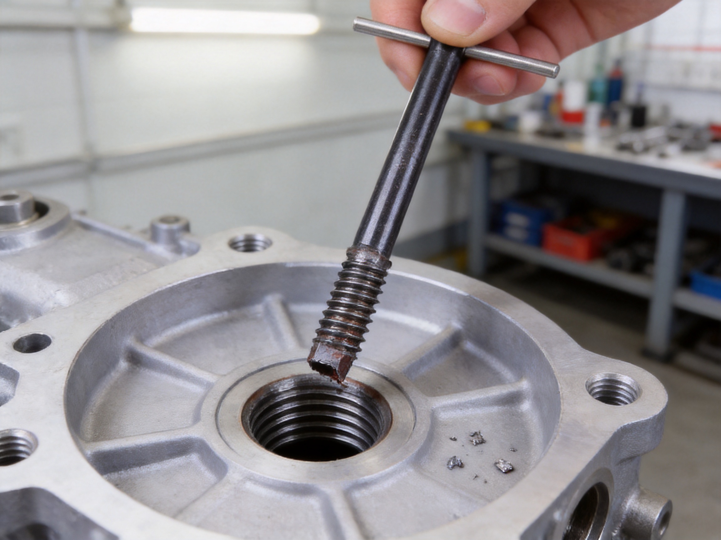
Manufacturing Strengths Behind the Product
The performance of a removal tool depends on more than its final shape. Material selection, machining accuracy, heat treatment, edge formation, dimensional inspection, and packaging all affect the user’s experience. Dongtai Jinzhize Metal Products Co., Ltd. operates as a specialized manufacturer of threaded connection products and related tools, allowing the Insert Removal Tool to be developed within an established threaded-product manufacturing environment.
Integrated Threaded-Product Expertise
The company produces helical wire inserts, self-tapping inserts, key-locking inserts, threaded adapters, oil plugs, installation taps, and related tools. This product scope provides direct knowledge of the components that the removal tool is intended to service. Understanding how an insert is formed, installed, compressed, locked, and removed helps inform the design of the gripping geometry and operating method.
A manufacturer focused on threaded connections can also better understand common field failures. These may include incorrect installation depth, cross-threading, insert deformation, locking feature damage, unsuitable hole preparation, improper tool selection, and excessive tightening. Such knowledge supports more practical product development than a general tool design approach that does not focus specifically on threaded insert systems.
Owned Manufacturing Facility
Established in 2015, Dongtai Jinzhize operates from an owned manufacturing plant covering approximately 10,000 square meters. The facility is equipped with hundreds of machine tools and automated production systems. This infrastructure supports the production of both standard products and customized threaded connection solutions.
An owned facility can provide closer control over production scheduling, process consistency, equipment maintenance, and quality records. It also helps the manufacturer coordinate multiple stages of production, including raw material preparation, machining, heat treatment arrangements, surface processing, inspection, assembly, and final packing.
For international buyers, manufacturing capacity is important because product reliability must be matched by supply reliability. A tool that performs well but cannot be supplied consistently may create delays in maintenance programs and production planning. Jinzhize’s manufacturing scale and annual output capability support stable supply for distributors, industrial users, and original equipment applications.
Automated and Repeatable Production
Automation can improve repeatability in operations that require stable dimensions and consistent positioning. For a removal tool, accurate working geometry is essential. Small variations in the cutting or gripping area may affect how the tool engages with an insert, particularly in smaller sizes.
Automated production systems can help control repeated machining operations and reduce variation between batches. They are most effective when supported by suitable process planning, calibrated equipment, trained operators, and documented inspection procedures. Automation does not replace technical judgment; instead, it provides a stable manufacturing platform on which skilled personnel can maintain process control.
Quality Management and Traceability
Threaded connection products are often used in critical assemblies, so consistent quality and traceability are important. Jinzhize emphasizes a rigorous quality management system and a comprehensive after-sales service mechanism. These systems support the identification of production batches, inspection records, customer requirements, and corrective actions when necessary.
Traceability is particularly valuable for industrial customers who purchase tools and inserts for regulated or quality-sensitive applications. If a performance issue occurs, traceable production information can help identify the affected batch, review process records, and implement an appropriate response. This approach supports long-term procurement confidence rather than one-time product sales.
Design, Development, and Production Team
The company has built an experienced team for product design, development, and manufacturing. A capable technical team can evaluate the relationship between tool geometry, material properties, insert types, base materials, and operating conditions. This is important because insert removal is not identical in every application.
For example, the force required to remove a wire insert from an aluminum housing may differ substantially from the force required to remove a locked insert from a steel component. The condition of the insert, the depth of installation, and the presence of corrosion or bonding material may also affect the process. Product development must therefore balance grip, toughness, dimensional accuracy, and ease of use.
Manufacturing Process Considerations
Material Preparation
The process begins with the selection and preparation of suitable alloy steel. The material must provide adequate hardness, toughness, machinability, and resistance to repeated contact with metal inserts. Incoming material control helps ensure that the selected steel meets the requirements for the intended production process.
Material identification and batch management support traceability. Proper preparation may include cutting stock to suitable dimensions, removing surface contamination, and preparing the material for machining. Consistency at this stage contributes to stable results in later operations.
Precision Machining
Machining creates the tool’s body, working profile, gripping edges, and functional interfaces. The dimensional relationship between these features must be controlled carefully. If the gripping area is too large, the tool may not engage the insert correctly. If it is too small, the tool may concentrate force excessively or slip during operation.
Modern machine tools and production planning help maintain repeatable dimensions. Depending on the product configuration, machining may include turning, milling, drilling, shaping, grinding, or other specialized operations. The sequence is selected to protect critical surfaces and maintain alignment between functional features.
Hardness and Heat Treatment Control
Heat treatment can improve the hardness and wear resistance of alloy steel. However, the process must be controlled to avoid excessive brittleness or dimensional distortion. The appropriate balance depends on the tool’s geometry and the stress applied during extraction.
After heat treatment, critical dimensions and working edges may require finishing operations. Inspection can include hardness verification, visual examination, dimensional measurement, and functional checks. These steps help confirm that the tool is both strong enough for service and accurate enough to engage the intended insert size.
Edge Finishing
The working edges must be sharp and properly formed to create a firm bite. At the same time, unnecessary burrs or irregularities can interfere with insertion into the damaged insert and may create uncontrolled contact with the base material. Edge finishing therefore requires attention to both sharpness and geometry.
Consistent edge finishing improves the repeatability of removal operations. It also helps the operator achieve engagement without excessive preparation or repeated trial-and-error adjustments.
Final Inspection and Packing
Final inspection verifies that the tool conforms to its intended dimensions, surface condition, hardness requirements, and appearance. Packaging should protect the working edges from impact, corrosion, and contamination during storage and transportation.
Clear identification is important when several removal tools are used together. Size and product information should remain legible throughout normal storage and handling. Proper packaging also supports international distribution by reducing the risk of damage during shipment.
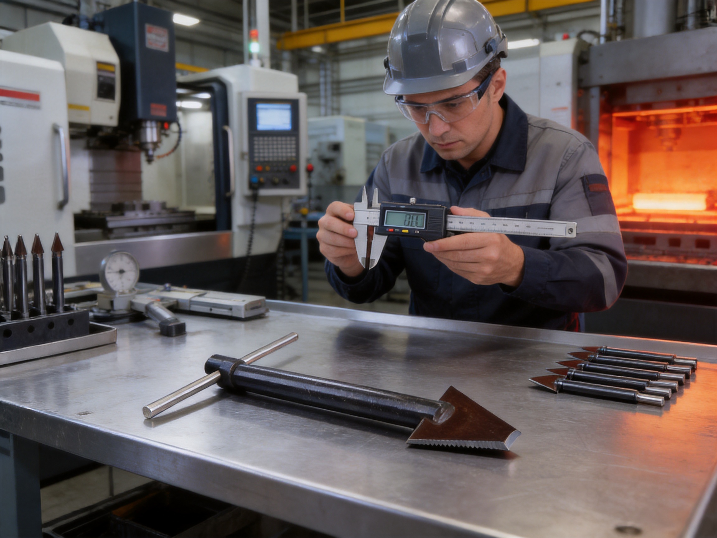
Recommended Operating Procedure
The exact procedure may vary according to the insert type and tool configuration, but a controlled removal process generally includes the following stages.
1. Identify the Insert
Determine the insert type, approximate thread size, installation depth, and condition. Check whether it is a wire insert, self-tapping insert, locking insert, or another design. Select the appropriate removal tool for the insert dimensions.
2. Clean the Working Area
Remove dirt, oil, loose chips, sealant, and other contamination from around the insert. A clean surface improves visibility and reduces the risk that debris will enter the base hole during extraction.
3. Inspect the Base Component
Check the surrounding material for cracks, distortion, corrosion, or previous repair damage. Confirm that the component is securely supported and that the operator has adequate access. If the part is installed in machinery, follow the applicable lockout, isolation, and safety procedures.
4. Engage the Removal Tool
Align the tool with the insert and engage the working edges carefully. Avoid forcing the tool at an angle. The tool should contact the insert as intended, without unnecessary pressure against the parent material.
5. Apply Gradual Extraction Force
Use a steady and controlled motion. If the insert does not move, stop and reassess the tool size, engagement, contamination, and condition of the component. Do not immediately increase force beyond the tool’s intended operating conditions.
6. Remove and Inspect the Insert
Once the insert has been extracted, remove it from the working area and inspect the base hole. Look for damaged threads, burrs, embedded chips, or material deformation. The hole should be cleaned before a replacement insert is installed.
7. Prepare for Replacement
If the base thread remains within acceptable condition, install the correct replacement insert using the appropriate installation tool and procedure. If the hole has been damaged, further repair or an engineering assessment may be necessary.
Operators should always use suitable personal protective equipment and follow the tool’s technical instructions. Eye protection is especially important because small metal fragments may be released during removal.
Application Areas
Mechanical Manufacturing
Mechanical manufacturing operations often use inserts to reinforce tapped holes or repair threads after machining errors. An insert may need to be removed when it is installed at the wrong depth, positioned incorrectly, or damaged during trial assembly. The removal tool allows the manufacturer to correct the problem while preserving the machined component whenever possible.
Automotive Repair
Automotive engines, transmissions, brackets, housings, and suspension components frequently contain threaded holes exposed to vibration, temperature changes, and repeated service. A damaged insert can prevent correct fastener installation and may interrupt vehicle production or repair.
The compact design is useful in workshops where technicians must work around partially assembled components. By reducing the need for aggressive drilling or component replacement, controlled insert extraction can shorten repair time and reduce material costs.
Industrial Equipment Maintenance
Industrial equipment may contain numerous threaded connection points, many of which are difficult to replace if damaged. Planned maintenance teams can use an insert removal tool to correct failed insert installations and restore equipment to service more efficiently.
The tool is also suitable for field service kits because it is compact and compatible with a broad range of sizes. Its application may include pumps, machine tools, fixtures, gearboxes, processing equipment, and maintenance assemblies.
Electronics and Instrumentation
Electronic housings and precision instruments may use small threaded inserts to provide durable fastening points in lightweight or soft materials. These components often have limited wall thickness and closely spaced holes, making uncontrolled removal particularly risky.
A tool designed for controlled engagement can help reduce damage to delicate housings. Operators should select the correct size and use low, gradual force appropriate to the base material.
Aerospace and Rail Vehicle Manufacturing
Aerospace and rail vehicle components require dependable threaded connections and careful control of repair processes. The manufacturer’s products are used in sectors that include aerospace and rail vehicle manufacturing, where traceability, consistency, and reliable supply are important considerations.
Before use in a regulated application, customers should confirm applicable specifications, qualification requirements, inspection procedures, and approval status. The removal tool can support maintenance and correction work, but the repair process must remain consistent with the engineering documentation governing the specific component.
Selection and Maintenance Guidance
Select the tool according to the actual insert size and design. M3–M16 compatibility covers many common applications, but the nominal thread diameter alone may not describe every relevant feature. Insert length, locking elements, installed depth, and damage condition can affect compatibility.
Keep the working edges clean and free of chips. After use, wipe the tool and apply suitable corrosion protection if required by the storage environment. Store it in a dry location, preferably in protective packaging that prevents the edges from contacting other metal tools.
Inspect the tool before each use. Look for chipped edges, deformation, cracks, excessive wear, corrosion, or looseness. A damaged tool should not be used because failure during extraction can damage the component or create a safety hazard.
Do not modify the tool by grinding away working areas, drilling new holes, welding, or applying unauthorized heat. Such modifications may change the force distribution and compromise the material properties established during manufacturing.
For high-volume use, maintenance departments should establish a simple inspection and replacement schedule. Recording the tool size, date of issue, number of operations, and observed condition can help identify wear trends and maintain consistent repair quality.
Quality, Supply, and Customization Support
Dongtai Jinzhize Metal Products Co., Ltd. supplies threaded connection and fastening products to the global market. Its product portfolio and manufacturing experience support customers that require more than a single standard tool. Depending on project requirements, buyers may seek coordinated supply of inserts, installation taps, removal tools, oil plugs, adapters, or locking products.
Coordinated sourcing can simplify purchasing and improve compatibility between the insert and the tools used to install or remove it. It also allows customers to discuss thread size, base material, installation conditions, packaging, inspection documentation, and supply schedules with a manufacturer familiar with the complete product family.
The company’s annual output value reached RMB 153 million in 2024, reflecting its ability to support large-scale and stable supply. Manufacturing capacity is supported by its owned plant, machine tool resources, automated production systems, experienced personnel, quality management, and after-sales service structure.
Customers requiring customized solutions should provide complete technical information, including thread standard, insert type, nominal size, material, operating temperature, installation depth, expected removal conditions, packaging requirements, and application environment. Detailed information allows the manufacturer to assess feasibility and recommend a suitable product configuration.
Frequently Asked Questions
What is an insert removal tool used for?
It is used to extract incorrectly installed, damaged, deformed, or stuck thread inserts from a tapped hole. The objective is to remove the insert while preserving the original base thread for inspection and possible replacement.
What insert sizes does this tool support?
The stated compatibility range is M3–M16. Users should still confirm the exact insert profile, length, locking features, and installed condition before operation.
Can the tool remove every type of thread insert?
No single tool should be assumed to remove every insert design under every condition. Compatibility depends on the insert structure and the tool configuration. The Insert Removal Tool is designed for a range of common thread insert removal tasks, but difficult or severely seized applications may require additional engineering assessment.
Will removal damage the original base thread?
The tool is designed to reduce the risk of damage through firm engagement and controlled force distribution. However, the final result depends on the insert condition, base material, installation history, corrosion, contamination, and operator technique. The hole should always be inspected after removal.
Can it be used on aluminum components?
It can support removal work on aluminum components when the correct size and procedure are used. Aluminum is relatively soft, so operators should avoid excessive force and should pay close attention to alignment and thread condition.
Is it suitable for field maintenance?
Yes. Its compact structure makes it convenient for maintenance kits, service vehicles, production lines, and on-site repair work. Adequate lighting, access, component support, and safety protection are still required.
What should be done if the insert does not move?
Stop and verify the tool size, engagement, insert type, and condition of the base component. Clean the area and check whether locking features, corrosion, adhesive, or deformation are preventing movement. Do not apply uncontrolled force or strike the tool unless the approved procedure specifically permits it.
How should the tool be stored?
Clean and dry the tool after use, protect the working edges, and store it in a dry environment. Avoid contact with loose tools that could damage the gripping surfaces.
Yes. Dongtai Jinzhize Metal Products Co., Ltd. manufactures a broader range of threaded connection products, including helical wire inserts, self-tapping inserts, key-locking inserts, threaded adapters, oil plugs, installation taps, and related tools.
What information is useful when requesting a quotation?
Provide the required quantity, insert type, nominal size, thread standard, application, base material, tool configuration, packaging requirements, inspection requirements, and desired delivery schedule. Technical drawings or photographs may also help clarify the application.
Conclusion
The Insert Removal Tool provides a practical solution for correcting failed insert installations and repairing threaded components. Its main advantages are high-hardness alloy steel construction, firm bite geometry, controlled force distribution, multi-size compatibility from M3 to M16, simple operation, and a compact structure suitable for workshop and field use.
Compared with improvised methods, the dedicated design offers better control and a lower risk of damaging the original base thread. This can reduce rework, shorten maintenance time, and help preserve expensive components. The tool is suitable for mechanical manufacturing, automotive repair, industrial equipment maintenance, electronics manufacturing, and other applications where reliable threaded connections are important.
Its development is supported by Dongtai Jinzhize Metal Products Co., Ltd.’s broader expertise in threaded connection products. Established in 2015, the company operates a 10,000-square-meter manufacturing facility with hundreds of machine tools and automated production systems. Its product development team, quality management system, traceability practices, and after-sales service structure support the consistent production and supply of threaded fastening solutions.
For companies seeking a reliable method to remove damaged or incorrectly installed thread inserts, the tool offers a focused combination of strength, precision, portability, and practical manufacturing support. Correct selection and careful operation remain essential, but the right dedicated extractor can turn a potentially costly component failure into a manageable repair.
References
1. General principles of threaded insert installation, inspection, and repair in mechanical assemblies.
2. Engineering guidance on alloy steel tool materials, hardness, toughness, and wear resistance.
3. Industrial maintenance practices for damaged threaded holes and insert replacement.
4. Quality management and traceability principles for manufactured fastening components.
5. Manufacturer product information for insert removal tools, threaded inserts, installation taps, and related fastening products.
6. Technical considerations for threaded connections in automotive, aerospace, rail vehicle, electronics, and industrial equipment applications.