Français
 Español
 Deutsch


Content
- 1 Why Thread Insert Removal Requires a Dedicated Tool
- 2 Product Overview
- 3 Key Advantages Over General-Purpose Removal Methods
- 4 Technical Design Features
- 5 Recommended Removal Procedure
- 6 Applications in Industrial Manufacturing
- 7 Manufacturing Strengths Behind the Product
- 8 Comparison with Alternative Removal Approaches
- 9 How the Tool Supports Lower Total Repair Cost
- 10 Selection Guidance for Buyers
- 11 Care, Storage, and Service Life
- 12 Quality and Supply Reliability
- 13 Safety and Operational Considerations
- 14 Frequently Asked Questions
- 14.1 What is an insert removal tool used for?
- 14.2 Which insert sizes can the tool remove?
- 14.3 Can it remove a helical wire insert?
- 14.4 Will the tool damage the original base thread?
- 14.5 What material is used to manufacture the tool?
- 14.6 Can it be used in automotive maintenance?
- 14.7 Is the tool suitable for electronics manufacturing?
- 14.8 How does it compare with drilling out an insert?
- 14.9 What should be done if the insert will not move?
- 14.10 Can one tool cover every thread insert application?
- 14.11 Why purchase the extractor from a threaded connection manufacturer?
- 14.12 How should the tool be stored?
- 15 Conclusion
- 16 References
- 17 Product: Insert Removal Tool
Threaded inserts are widely used to restore, reinforce, and standardize tapped holes in components made from aluminum, magnesium, cast iron, steel, plastics, and other engineering materials. When correctly installed, an insert creates a durable internal thread that can withstand repeated assembly, vibration, thermal cycling, and service loads. However, even a well-designed threaded connection may eventually require repair. An insert can be installed at the wrong depth, damaged during assembly, deformed by excessive torque, contaminated by corrosion, or locked in place after long-term service. Removing such an insert without harming the parent material requires the correct tool, controlled force, and a suitable extraction method.
The insert removal tool is developed specifically for this task. It is intended to remove incorrectly installed, damaged, worn, or stuck thread inserts while protecting the original threads in the base hole. Unlike improvised screwdrivers, punches, pliers, or general-purpose gripping tools, a dedicated insert extractor engages the insert in a controlled manner. Its working edges are designed to bite securely into the insert structure, transfer force efficiently, and reduce the risk of slipping or damaging the surrounding material.
For industrial production, equipment maintenance, automotive repair, electronics manufacturing, and metalworking operations, this type of tool can reduce rework time and prevent the unnecessary replacement of expensive components. It also supports a more consistent repair process. When used together with wire thread inserts, self-tapping inserts, key-locking inserts, installation taps, and related fastening products, it becomes part of a complete threaded connection and maintenance system.
Why Thread Insert Removal Requires a Dedicated Tool
Thread inserts are normally installed to improve the performance of a tapped hole. Helical wire inserts, self-tapping inserts, and key-locking inserts are manufactured to remain firmly engaged with the parent material. That retention is essential during normal use, but it makes removal difficult when an insert has to be replaced.
A damaged insert may no longer accept the original fastener, but it can still remain tightly anchored in the base hole. If a conventional tool is forced against it, several problems may occur. The tool may slip and mark the component surface. The insert may collapse into the hole instead of being extracted. The base thread may be cut, stretched, or distorted. In soft materials such as aluminum, the surrounding hole may be damaged before the insert begins to move. Once this happens, a simple insert replacement may become a larger repair involving oversize drilling, re-tapping, component replacement, or the use of a larger repair insert.
A specialized extractor addresses these risks through controlled engagement. Its geometry allows the tool to grip the insert rather than simply press against it. Force is concentrated at the appropriate contact points and distributed through the tool body. This helps the operator apply removal torque or axial force gradually. The result is a more predictable extraction process with less dependence on improvised techniques.
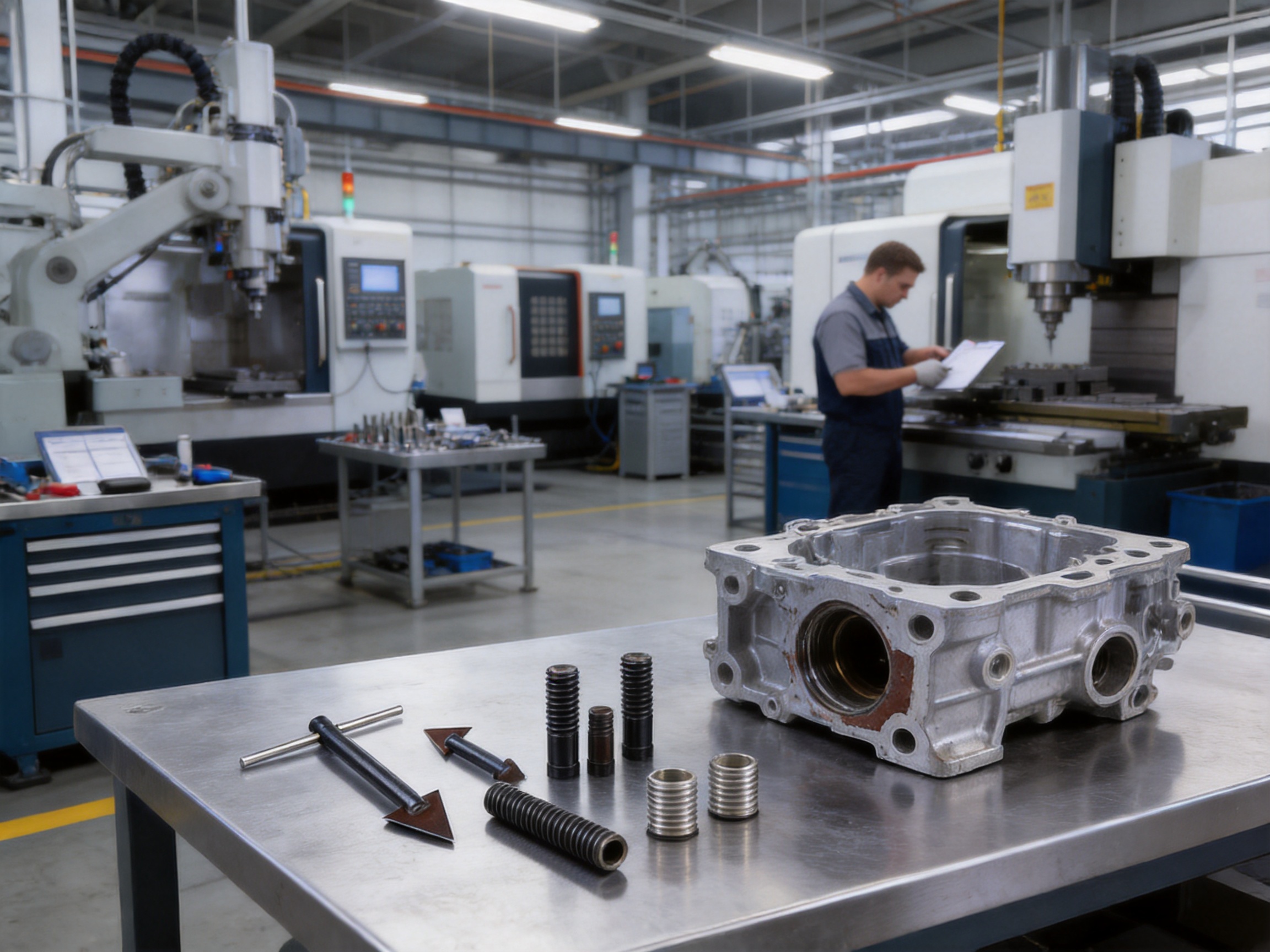
Another important consideration is repeatability. In a production or maintenance environment, operators may need to remove several inserts of different sizes. A dedicated tool system covering M3 through M16 inserts provides a standardized method for different repair situations. Instead of creating a new removal method for every component, the technician can select the appropriate size, engage the insert, and follow a consistent procedure.
Product Overview
The insert removal tool is a compact extraction instrument for removing thread inserts from prepared holes. It is suitable for incorrectly installed inserts, damaged inserts, worn inserts, and inserts that have become stuck during service. The tool is designed for use with multiple insert sizes from M3 to M16, helping maintenance teams address a broad range of threaded connection requirements.
The product is made from high-hardness alloy steel. This material selection provides a balance of wear resistance, impact resistance, and structural strength. During extraction, the tool may experience concentrated loads, intermittent shock, and repeated contact with hard metallic insert materials. A high-hardness alloy steel body and working edge help the tool maintain its functional profile under these conditions.
The working end is designed to match the insert thread structure closely. This firm-bite design helps prevent slippage during extraction. Secure engagement is particularly important when dealing with inserts that are damaged, partially stripped, corroded, or installed below the recommended depth. By keeping the extraction force closer to the insert axis, the tool can reduce unnecessary contact with the parent component.
The compact structure makes the tool easy to transport, store, and use at the worksite. It can be included in a maintenance kit, production-line repair station, vehicle service toolbox, or field service case. Its practical size is useful where access around the threaded hole is limited and where a large extraction fixture would be inconvenient.
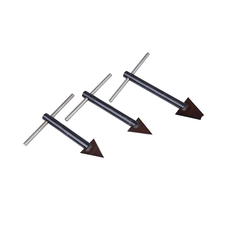
Insert Removal Tool
Key Advantages Over General-Purpose Removal Methods
Protection of the Parent Material
The primary advantage of a dedicated insert removal tool is its ability to protect the original hole. The base material often has greater value than the insert itself. In an automotive engine, transmission housing, aircraft component, industrial mold, or electronic enclosure, damage to the parent material can cause substantial cost and downtime.
A general-purpose tool may apply force to the wrong area of the hole. It may scrape the surrounding surface, enlarge the opening, or deform the internal thread. The insert removal tool is intended to engage the insert directly. This reduces the likelihood that the extraction process will transfer uncontrolled force to the base thread.
Protecting the parent material also improves the possibility of installing a replacement insert. If the original hole remains within acceptable dimensional and thread requirements, the technician can clean the hole, inspect it, and install a new insert without changing the repair design. This preserves the original component and reduces material consumption.
Controlled Force Distribution
Extraction force must be strong enough to overcome the insert’s retention, but excessive force can damage both the insert and the base hole. The tool’s gripping and force-distribution design helps the operator apply force in a more controlled manner. Instead of relying on a single sharp contact point or an unstable lever, the extractor transfers load through its body and working edges.
Controlled force is especially valuable when the insert is stuck by corrosion, contamination, galling, thread deformation, or incorrect installation. In these cases, a sudden movement can cause the tool to jump out of engagement. A firm-bite design gives the operator a better chance of maintaining contact while applying gradual force.
Reduced Slippage
Slippage is one of the most common causes of secondary damage during insert removal. When a tool slips, the operator may lose control of the extraction direction. The surrounding surface can be scratched, the insert can become more deformed, and the tool itself may be damaged.
The cutting edges of the insert removal tool are shaped to closely match the insert threads. This helps the tool penetrate or grip the insert wall and maintain contact during operation. The result is a more stable connection between the tool and the damaged insert. Although correct alignment and appropriate operating technique remain important, the tool’s geometry gives the operator a stronger starting point than a generic gripping device.
Multi-Size Compatibility
A repair department may work with small electronic assemblies one day and large industrial or automotive components the next. A removal solution limited to one insert dimension may be unsuitable for many service situations. Compatibility with M3–M16 thread inserts expands the tool’s usefulness across different applications.
Multi-size capability can also simplify purchasing and inventory management. Instead of relying on unrelated tools from different sources, a maintenance team can organize a consistent range of extraction tools for commonly used metric insert sizes. This supports faster tool selection, easier operator training, and more consistent repair documentation.
Time Savings During Maintenance
Removing a failed insert without the correct equipment can consume more time than installing the replacement. Operators may need to drill, cut, pry, or experiment with different tools. These steps increase the risk of damage and create uncertainty about the final condition of the hole.
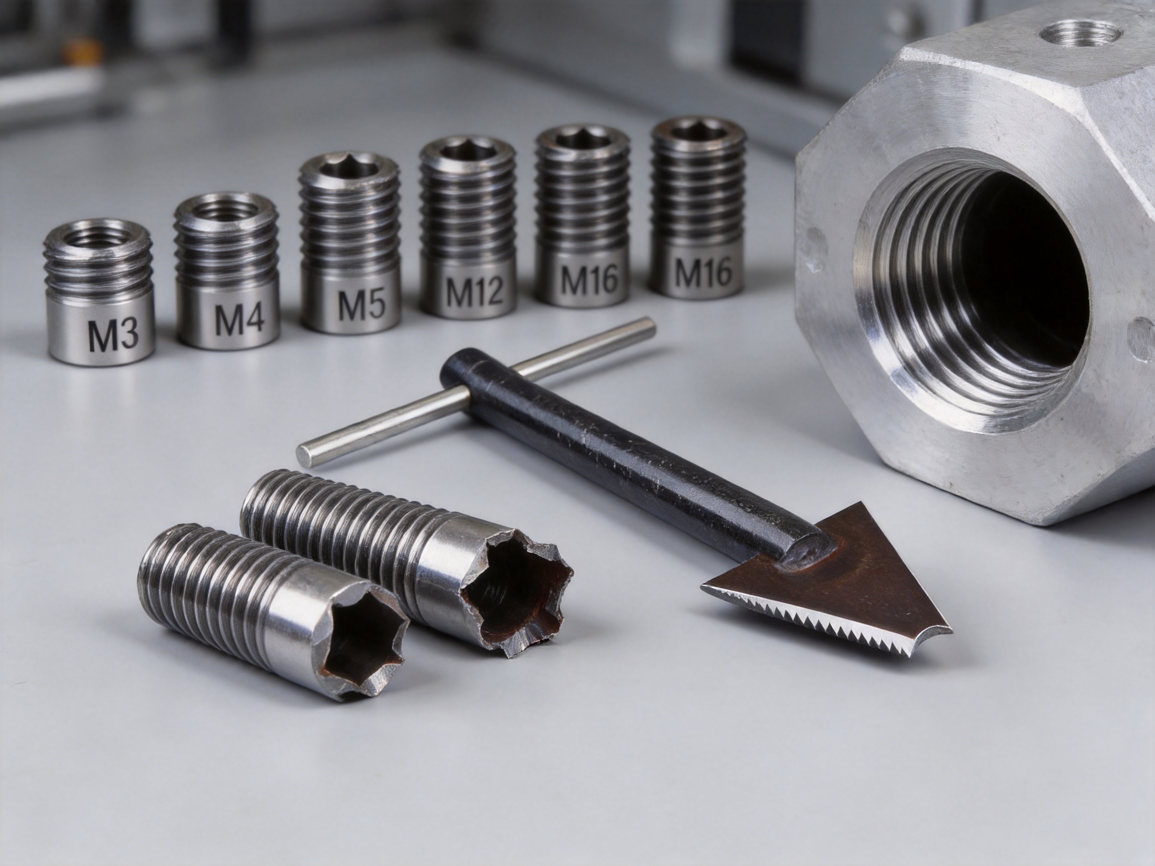
The insert removal tool simplifies the process into a controlled sequence: identify the insert, select the correct extractor size, engage the working end, apply gradual removal force, and inspect the hole after extraction. This streamlined approach can shorten repair time and help return equipment to service more quickly.
Compact and Field-Ready Construction
Large extraction machines are not always available where repairs occur. Automotive service technicians, industrial maintenance teams, and field engineers may need to work at the production line, inside a machine enclosure, near a vehicle, or at a remote installation site. A compact removal tool can be carried directly to the equipment.
Its compact structure also reduces storage requirements. The tool can be placed in a dedicated insert installation case, a machine maintenance cabinet, or a mobile service kit. This availability is important because damaged inserts are often discovered during assembly or scheduled maintenance rather than in a specialized workshop.
Technical Design Features
High-Hardness Alloy Steel
The working portion of an extractor must resist wear because it repeatedly contacts metallic inserts. It must also withstand impact and torsional loading when a stuck insert requires additional force. High-hardness alloy steel is suitable for this type of duty because it offers strong resistance to edge deformation and surface wear.
Material hardness alone does not determine tool performance. The steel must also be processed correctly so that the tool has an appropriate balance between hardness and toughness. Excessive hardness without sufficient toughness may make an edge brittle. Insufficient hardness may cause the gripping profile to wear quickly. A controlled manufacturing process is therefore essential for achieving a reliable working tool.
Thread-Matched Gripping Geometry
The tool’s gripping edges are designed around the geometry of thread inserts. This enables contact with the insert rather than random contact with the base hole. A close fit helps the tool remain engaged when the insert has lost its original shape or when the insert is stuck under load.
Thread-matched geometry also improves force transfer. When contact is distributed along suitable areas of the insert, the operator can apply removal force with less tendency for the tool to rotate away from the engagement point. This is important when the insert is small, when access is restricted, or when the insert has been damaged by a fastener.
Stable Force Transmission
During extraction, the tool body must transmit force from the operator to the insert without excessive flexing or unwanted movement. A stable structure improves control and reduces the risk that force will be concentrated at an unintended point.
Reliable force transmission is valuable in both manual and production maintenance operations. It gives experienced technicians the control needed for difficult repairs and makes the procedure easier for less experienced users who are following a standard work instruction.
Compact Structural Layout
The compact form of the removal tool supports access to recessed or crowded areas. Automotive engines, transmission housings, industrial fixtures, and electronic assemblies often contain nearby walls, brackets, wiring, or other components. A large tool may not align correctly with the damaged insert. A compact extractor is easier to position and reduces the need to disassemble surrounding parts.
Compact construction also makes it easier to protect the tool from contamination. When stored in a case or maintenance cabinet, the tool occupies limited space and can remain with the related installation taps and insert kits.
| Feature | Functional Benefit | Typical Maintenance Value |
|---|---|---|
| High-hardness alloy steel | Resists wear, impact, and edge deformation | Longer service life under repeated use |
| Firm-bite working edges | Engage damaged or stuck inserts securely | Lower risk of slippage during extraction |
| Controlled force distribution | Transfers load more evenly to the insert | Helps protect the original base threads |
| M3–M16 compatibility | Covers multiple metric insert sizes | Supports diverse production and repair work |
| Compact structure | Fits tool kits and restricted work areas | Convenient field and on-site maintenance |
| Simple operating sequence | Reduces unnecessary preparation steps | Shortens insert replacement time |
Recommended Removal Procedure
A removal tool performs best when the operator follows a controlled procedure. The exact steps may vary according to the insert type, base material, installation depth, and access conditions, but the following sequence provides a practical general method.
1. Identify the Insert and Inspect the Area
Before selecting a tool, determine the insert’s nominal size and type. Confirm whether it is a helical wire insert, self-tapping insert, key-locking insert, or another threaded insert design. Inspect the surrounding component for cracks, burrs, deformation, corrosion, adhesive, or foreign material.
Examine the insert opening and determine whether the insert is installed flush, below the surface, or above the surface. Check whether a fastener remains inside the insert. If a fastener is present, remove it carefully before attempting extraction whenever possible.
2. Select the Correct Tool Size
Select an extractor that corresponds to the insert size. For applications within the M3–M16 range, correct size selection helps the working edges engage the insert properly. An undersized tool may fail to grip securely, while an oversized tool may contact the base material or damage the insert opening.
If the insert is heavily deformed, the operator should select the closest suitable tool and examine the contact area carefully before applying force. When the insert condition is uncertain, a trial engagement with light pressure is preferable to immediate high-force operation.
3. Clean the Threaded Opening
Remove chips, grease, oxidation, and loose material from the opening. Cleaning improves visibility and allows the extractor to reach the intended engagement area. A clean work area also makes it easier to inspect the original base thread after the insert has been removed.
Cleaning should be performed with a method compatible with the component. Avoid introducing particles into sensitive assemblies, especially electronic devices, hydraulic systems, precision mechanisms, and sealed equipment.
4. Align the Extractor
Position the extractor along the axis of the insert. Correct alignment helps the tool engage evenly and reduces side loading. If the tool is tilted, the gripping edges may contact only one side of the insert. This can increase the risk of slippage or localized damage.
Where access is restricted, take time to establish a stable working position. The operator should be able to apply force gradually without losing control of the tool or striking nearby components.
5. Engage the Working Edges
Press or turn the extractor as required by its operating design until the gripping edges obtain firm contact with the insert. Do not begin with excessive force. The objective is to establish a positive bite before increasing the removal load.
Once engaged, check that the tool is not contacting the base thread or surrounding surface. A stable engagement point should remain in place when light manual pressure is applied.
6. Apply Gradual Removal Force
Apply force slowly and steadily. If the insert begins to move, continue with controlled motion rather than using sudden impacts. If the insert does not move, stop and reassess the condition. Additional force may be appropriate in some situations, but the operator should first check for corrosion, thread distortion, adhesive, or incorrect tool alignment.
Excessive force can damage the insert, the extractor, or the component. The purpose of a dedicated removal tool is to improve control, not to eliminate the need for careful operation.
7. Inspect the Hole After Extraction
After removing the insert, inspect the base hole for damaged threads, burrs, metal fragments, or remaining insert material. Check the hole depth and confirm that the original thread is suitable for a replacement insert. If the base material is damaged, the repair may require reworking before a new insert is installed.
Clean the hole thoroughly and verify that the replacement insert matches the required size, length, material, and locking configuration. A correct inspection step prevents a second failure caused by installing a new insert into a contaminated or damaged hole.
Applications in Industrial Manufacturing
Mechanical Manufacturing
Machined components often use threaded inserts when the base material is too soft for repeated fastening or when a standardized internal thread is required. During production, an insert may be installed incorrectly because of depth variation, tool wear, operator error, contamination, or incorrect component orientation. A removal tool allows the part to be corrected instead of discarded.
In small-batch manufacturing, maintaining repair flexibility is particularly important. A component may have a long machining lead time or involve expensive raw material. Removing a failed insert and restoring the hole can protect the value already invested in the part.
Automotive Engines and Transmissions
Automotive components experience vibration, temperature changes, repeated service operations, and exposure to oils or other contaminants. Thread inserts are used in housings, covers, mounting points, engine components, and transmission structures. If an insert is damaged during assembly or service, the component may be unavailable until the threaded hole is repaired.
The compact size of the extractor is useful in automotive repair because access around engines and transmissions is often limited. A controlled tool can help technicians remove the damaged insert while avoiding unnecessary disassembly. This may reduce vehicle downtime and support repair rather than component replacement.
Industrial Equipment Maintenance
Industrial equipment may contain hundreds or thousands of threaded connections. A damaged insert can interrupt production if it affects a guard, fixture, actuator, enclosure, bearing housing, or structural assembly. Maintenance teams benefit from having a reliable extraction method available near the equipment.
Because the tool is suitable for multiple sizes, it can serve a range of machines without requiring a separate specialized solution for every threaded hole. This is practical for maintenance departments that support diverse equipment and need a compact, organized toolkit.
Electronics Manufacturing
Electronic devices and assemblies frequently use small threaded holes in housings, brackets, heat sinks, and structural frames. These components may be made from aluminum alloys, zinc alloys, plastics, or other materials that can be damaged by uncontrolled force.
A small insert removal tool can help correct assembly errors while reducing the risk of marking the enclosure or enlarging the hole. Operators must take particular care to prevent metal particles from entering sensitive electronic areas. Proper cleaning, masking, and post-removal inspection should be included in the work instruction.
Aerospace and Rail Vehicle Manufacturing
Aerospace and rail vehicle applications place high demands on traceability, repeatability, and component preservation. Threaded connection products are used in structural parts, panels, brackets, equipment mounts, and serviceable assemblies. When a threaded insert must be replaced, the repair method should minimize damage to the parent component and provide a clear inspection record.
A dedicated extractor supports controlled maintenance, but the user must always follow the applicable engineering documentation, approved repair procedures, and material-specific requirements. Tool capability does not replace the need for qualified personnel and application approval.
Manufacturing Strengths Behind the Product
The performance of an insert removal tool depends on more than its visible shape. Material selection, machining accuracy, heat treatment, edge preparation, inspection, and packaging all influence whether the tool will perform consistently. A manufacturer with experience in threaded connection products can design the tool in relation to the inserts it is intended to remove.
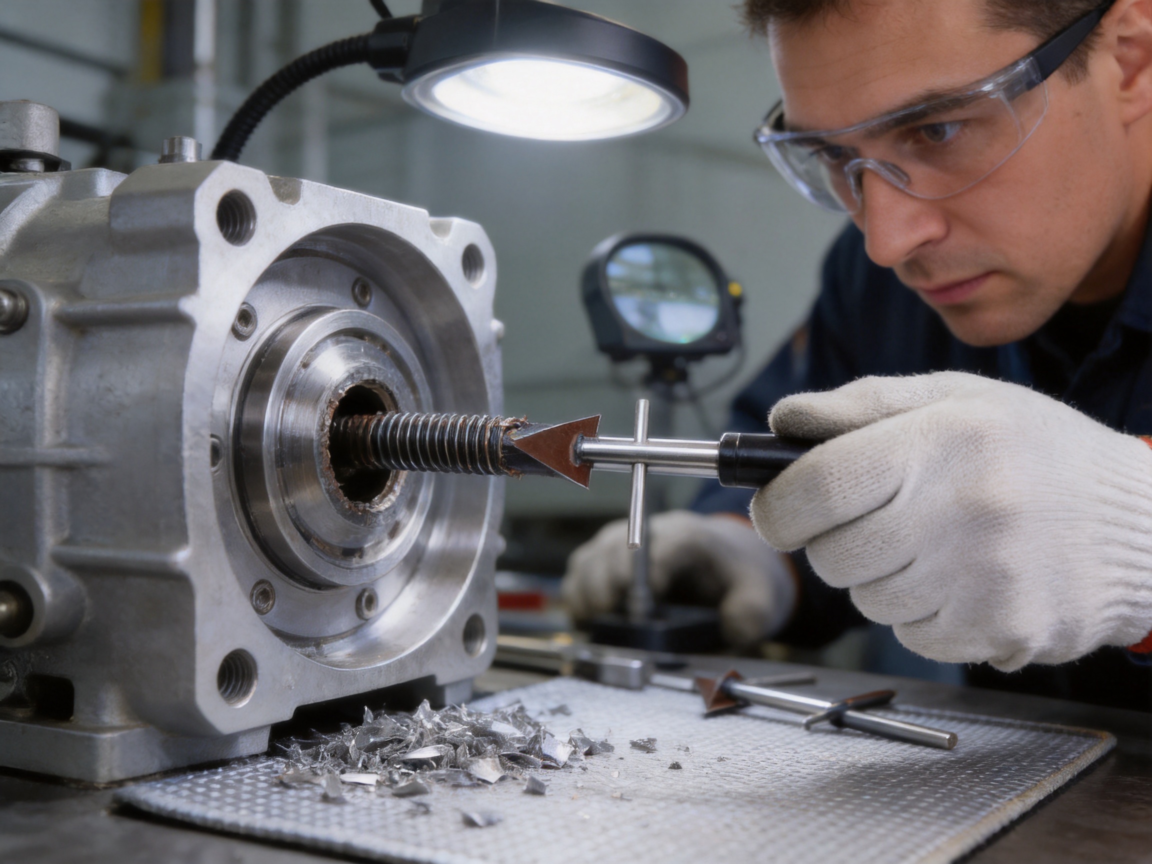
Dongtai Jinzhize Metal Products Co., Ltd. operates as a specialized manufacturing facility for threaded connection products and related tools. Established in 2015, the company focuses on helical wire inserts, self-tapping inserts, key-locking inserts, threaded adapters, oil plugs, installation taps, and complementary products. This product concentration provides practical knowledge of insert geometry, installation behavior, thread dimensions, and repair requirements.
The company operates a 10,000-square-meter owned manufacturing plant equipped with hundreds of machine tools and automated production systems. This infrastructure supports stable production capacity and provides the equipment base required for repeatable machining operations. For customers purchasing removal tools together with inserts and installation equipment, the manufacturer’s broader product range can also simplify technical coordination.
In 2024, the company achieved an annual output value of 153 million RMB. This figure reflects the company’s ability to support large-scale and stable supply across its threaded connection product categories. Production capability is important for distributors, industrial customers, and original equipment manufacturers that require dependable replenishment rather than occasional spot purchasing.
Design and Development Capability
A dedicated design and development team helps connect customer requirements with practical product improvements. Insert removal is not the same in every application. The tool must account for different insert sizes, materials, thread forms, installation depths, access conditions, and failure modes. Experience across related insert products allows a manufacturer to evaluate these factors more effectively.
Product development can include improvements to gripping geometry, tool hardness, handle or body configuration, size coverage, packaging, and compatibility with existing maintenance procedures. The objective is not merely to produce a tool that can remove an insert once, but to create a product that performs reliably across repeated professional use.
Automated Production Systems
Automated production systems can improve consistency in repeated machining and processing operations. For a precision tool, consistency matters because small differences in working geometry may affect engagement, force transfer, and service life. Automation can support stable production parameters while skilled personnel oversee equipment operation, process controls, and inspection.
Automation also helps manufacturers respond to larger orders and maintain delivery stability. This is relevant when customers need a complete range of M3–M16 removal tools or require regular supply for multiple production sites.
Quality Management and Traceability
The company maintains a rigorous quality management system and a comprehensive after-sales service mechanism. For industrial customers, quality management is valuable because the tool may become part of a documented repair process. Consistent product identification, inspection, packaging, and customer support help reduce uncertainty during procurement and use.
Traceable products are particularly important in automotive, aerospace, rail, and other industries where maintenance activities may require records of the tool, component, operator, and repair method. The exact documentation required depends on the customer’s quality system, but a manufacturer committed to traceability is better positioned to support such requirements.
Comparison with Alternative Removal Approaches
Improvised Screwdriver or Punch Methods
An improvised screwdriver or punch may appear convenient because it is already available in the workshop. However, these tools are not designed to match the insert thread or distribute extraction force. They may deform the insert, slip into the base thread, or damage the component surface.
Such methods can sometimes be used in emergency situations, but they offer limited repeatability. A purpose-built extractor is generally a better choice when component value, repair quality, and operator safety are important.
General-Purpose Pliers
Pliers work well when an exposed part can be gripped from the outside. Most installed thread inserts, however, are located inside a tapped hole and provide little accessible surface. Pliers may also crush the insert without creating a controlled extraction path.
The insert removal tool is designed for internal engagement. Its working edges reach the insert where general-purpose pliers cannot grip effectively.
Drilling Out the Insert
Drilling is sometimes used when an insert is severely damaged, but it carries a significant risk of damaging the base hole. The drill must remain precisely centered, and the operator must control depth carefully. Metal chips may enter surrounding equipment, and the repair may require additional tapping or enlargement.
A dedicated extractor can often remove the insert without cutting through the original hole. This preserves more of the parent material and may reduce the number of subsequent repair operations.
Heat or Chemical Loosening
Heat, penetrating fluids, or chemical treatments may help in certain cases, especially when corrosion or adhesive contributes to the problem. However, these methods may be unsuitable for plastics, electronic assemblies, painted parts, seals, lubricated systems, or temperature-sensitive components.
The insert removal tool provides a mechanical solution that can be used without introducing chemicals or high heat. Where additional treatment is approved, it can be combined with the extractor to improve the likelihood of controlled removal.
Single-Size Specialty Tools
A single-size extractor may perform well for one particular insert, but it does not address the needs of a varied production environment. The M3–M16 size range provides broader usefulness and helps maintenance teams establish a more complete repair capability.
| Removal Approach | Main Limitation | Advantage of a Dedicated Insert Extractor |
|---|---|---|
| Improvised punch | Unstable contact and possible base-thread damage | Purpose-designed engagement and controlled force |
| General-purpose pliers | Limited access to internal inserts | Designed for internal insert gripping |
| Drilling | Risk of enlarging or damaging the original hole | Mechanical extraction without cutting through the base |
| Heat or chemicals | May damage sensitive components or finishes | Mechanical method without heat or chemical exposure |
| Single-size tool | Limited application range | M3–M16 compatibility for broader use |
How the Tool Supports Lower Total Repair Cost
The purchase price of a removal tool is only one part of its value. The larger benefit may come from avoiding component replacement, reducing machine downtime, and preventing secondary damage. If a damaged insert causes an expensive housing or structural part to be rejected, the cost of the failed insert becomes insignificant compared with the cost of the complete component.
Controlled extraction helps preserve the possibility of repair. When the original base hole remains usable, the operator may install a replacement insert with limited additional work. This can reduce labor, material consumption, logistics, and production disruption.
Time savings also influence total cost. A maintenance team that spends an hour experimenting with improvised methods may incur more expense than a team that uses a suitable tool and completes the repair in a short, standardized sequence. Faster repairs can be particularly valuable on production lines where equipment downtime affects multiple operations.
Tool durability contributes to long-term value as well. High-hardness alloy steel and wear-resistant working edges support repeated use. A durable extractor is less likely to require frequent replacement and is more suitable for shared industrial tool inventories.
Inventory efficiency is another consideration. A multi-size tool range can support many repair tasks without requiring a large collection of unrelated products. When paired with compatible installation tools and thread inserts, the resulting maintenance system can be easier to organize and manage.
Selection Guidance for Buyers
Confirm the Thread Size Range
Before purchasing, identify the insert sizes most commonly used in the application. The M3–M16 range covers many metric industrial requirements, but customers should confirm the exact dimensions, insert type, and working depth before placing an order.
Consider the Base Material
The base material affects removal difficulty and the risk of damage. Soft aluminum and magnesium alloys require particularly careful force control. Steel and cast iron may provide stronger support but can create greater resistance when the insert is seized. The selected tool should be used in accordance with the material and approved repair procedure.
Evaluate Access Conditions
Measure the available space around the threaded hole. Compact tools are advantageous in crowded assemblies, but the operator must still have enough room to align and actuate the extractor. Customers should consider whether the insert is recessed, surrounded by walls, or located near wiring and other sensitive parts.
Review Expected Usage Frequency
Occasional users may require a basic size range for workshop emergencies. High-volume production and maintenance departments may need complete sets, spare tools, labeled storage, inspection procedures, and replenishment support. Discussing usage frequency with the manufacturer can help determine the appropriate supply configuration.
Consider Complete Threaded Connection Support
Customers may benefit from sourcing removal tools from a manufacturer that also produces wire inserts, self-tapping inserts, key-locking inserts, threaded adapters, oil plugs, installation taps, and other related products. A broader product portfolio can reduce compatibility concerns and simplify communication regarding thread standards, insert dimensions, and installation procedures.
Care, Storage, and Service Life
After use, remove metal particles and contamination from the working edges. Inspect the gripping profile for wear, deformation, cracks, or chipped areas. A damaged extractor should not be returned to service because reduced engagement may increase the chance of slippage.
Store the tool in a dry, organized location. Keeping the extractor with abrasive chips, moisture, or corrosive chemicals can shorten its service life. If the tool is part of a multi-size set, label each size clearly to reduce selection errors.
Do not use the tool as a general-purpose punch, pry bar, or striking instrument unless the product instructions specifically allow that operation. The working edges are designed for insert extraction, and misuse may damage the tool or reduce its accuracy.
Maintenance departments should consider adding the extractor to a periodic tool inspection program. Inspection intervals can be based on usage frequency, extraction force, working environment, and internal quality requirements. Recording tool condition helps identify wear trends and supports timely replacement.
Quality and Supply Reliability
For industrial buyers, product performance and supply reliability are closely connected. A tool that performs well but cannot be replenished consistently may create difficulties for multiple production sites. A manufacturer with an owned production plant, extensive machine capacity, automated systems, and established threaded product lines can provide stronger support for repeat orders.
Dongtai Jinzhize Metal Products Co., Ltd. has developed its business around threaded connection and fastening products for global customers. Its products are used in automotive, aerospace, rail vehicle, industrial, and other demanding applications. The company’s manufacturing scale and product specialization support both standard supply and broader threaded connection programs.
The company’s mission is to provide stable and reliable threaded connection and fastening products for critical assemblies. In the context of insert removal tools, this means focusing on consistent working performance, practical application, and service support. Its after-sales mechanism is intended to help customers resolve product, application, and procurement questions during long-term cooperation.
For distributors and original equipment manufacturers, the ability to obtain related items from one specialized supplier may improve sourcing efficiency. A customer may require thread inserts, installation taps, insertion tools, removal tools, oil plugs, or custom threaded components for the same project. Coordinated supply can reduce the need to manage multiple technical interfaces.
Safety and Operational Considerations
Operators should wear appropriate eye protection during insert removal because small metal fragments may be released. Gloves may be suitable depending on the work environment, but they should not reduce tool control. The component should be securely supported so that it does not move unexpectedly during extraction.
Before beginning work, isolate machinery and confirm that no electrical, hydraulic, pneumatic, or mechanical energy can create a hazard. For vehicle and industrial equipment repairs, follow the relevant lockout, isolation, and service procedures.
Never position fingers near the working edges while force is being applied. Use the correct size and keep the tool aligned with the insert. If the insert does not move under reasonable controlled force, stop and evaluate the cause rather than increasing force without limit.
Where the component is safety-critical or subject to regulatory control, removal and replacement should be performed by qualified personnel according to approved engineering instructions. The tool supports the repair process, but it does not replace inspection, dimensional verification, or application-specific approval.
Frequently Asked Questions
What is an insert removal tool used for?
It is used to extract incorrectly installed, damaged, worn, or stuck thread inserts from a component. The tool is designed to grip the insert and remove it while reducing the risk of damage to the original threads in the base hole.
Which insert sizes can the tool remove?
The product is suitable for multiple metric insert sizes from M3 to M16. The operator should select the tool that corresponds to the insert size and confirm compatibility with the specific insert design before use.
Can it remove a helical wire insert?
It is designed for thread insert extraction and is suitable for applications involving wire thread inserts when the correct tool size and operating method are used. The condition of the insert, installation depth, and base material should be assessed before removal.
Will the tool damage the original base thread?
The tool is designed to protect the original base thread through controlled gripping and force distribution. However, final results depend on correct alignment, size selection, insert condition, and operator technique. The hole should always be inspected after extraction.
What material is used to manufacture the tool?
The tool is manufactured from high-hardness alloy steel. This material provides wear resistance, impact resistance, and durability for repeated insert removal operations.
Can it be used in automotive maintenance?
Yes. The tool is suitable for automotive repair and maintenance applications, including threaded components in engines, transmissions, housings, and related assemblies. Technicians should follow vehicle-specific service procedures and protect nearby components from metal particles.
Is the tool suitable for electronics manufacturing?
Yes. It can be used for damaged inserts in electronic devices, housings, brackets, and metal structures. Because electronics may be sensitive to metal debris and mechanical impact, the work area should be protected and cleaned carefully after extraction.
How does it compare with drilling out an insert?
Drilling can remove an insert, but it may enlarge or damage the base hole and can create chips that enter the equipment. A dedicated extractor provides a controlled mechanical alternative that is intended to preserve the original hole whenever possible.
What should be done if the insert will not move?
Stop and check the tool size, alignment, insert condition, corrosion, contamination, and installation depth. Additional treatment may be appropriate for some applications, but heat, chemicals, or impact should only be used when approved for the component and insert type.
Can one tool cover every thread insert application?
No single tool is suitable for every possible insert design, size, or failure condition. The M3–M16 product range covers many metric requirements, but buyers should confirm the exact insert type, dimensions, and application before selecting the appropriate extractor.
Why purchase the extractor from a threaded connection manufacturer?
A specialized threaded connection manufacturer understands insert geometry, installation behavior, tool compatibility, and repair requirements. This can simplify technical communication and allow customers to source related products such as wire inserts, self-tapping inserts, key-locking inserts, installation taps, and threaded adapters.
How should the tool be stored?
Clean the tool after use, remove metal particles, inspect the working edges, and store it in a dry, organized location. Avoid using the extractor for unrelated tasks, and replace it if the gripping edges become cracked, chipped, or excessively worn.
Conclusion
The insert removal tool provides a controlled and practical method for extracting damaged, incorrectly installed, worn, or stuck thread inserts. Its high-hardness alloy steel construction, firm-bite gripping design, controlled force distribution, M3–M16 compatibility, and compact structure make it suitable for industrial production, automotive repair, electronics manufacturing, equipment maintenance, mechanical manufacturing, and other threaded connection applications.
Compared with improvised punches, general-purpose pliers, uncontrolled drilling, and single-size removal methods, a dedicated extractor offers better engagement, lower slippage risk, improved protection of the parent material, and greater process repeatability. These advantages can reduce repair time, protect expensive components, and support the installation of replacement inserts without unnecessary enlargement of the original hole.
The product is supported by the manufacturing capabilities of Dongtai Jinzhize Metal Products Co., Ltd., a specialized producer of threaded connection and fastening products. Established in 2015, the company operates a 10,000-square-meter owned facility with hundreds of machine tools and automated production systems. Its experience in wire inserts, self-tapping inserts, key-locking inserts, threaded adapters, oil plugs, installation taps, and related tools provides a strong technical foundation for producing practical extraction equipment.
For customers seeking dependable threaded connection solutions, the removal tool can serve as an important part of a complete maintenance system. When combined with suitable inspection, cleaning, installation, and quality procedures, it helps extend component service life and improve the reliability of repaired threaded assemblies.
References
1. General principles of threaded insert installation, inspection, and repair in mechanical assemblies.
2. Industrial maintenance practices for damaged and failed threaded connections.
3. Engineering guidance on alloy steel tool materials, hardness, wear resistance, and toughness.
4. Automotive service procedures for repairing threaded holes in engine and transmission components.
5. Manufacturing quality management and traceability practices for precision metal products.
6. Technical information supplied for the insert removal tool and associated threaded connection products.
7. Product and company information provided by Dongtai Jinzhize Metal Products Co., Ltd.